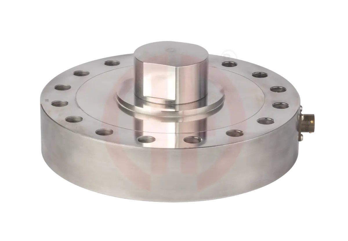
Load Cell Trouble Shooting Guide
Faulty Load Cell will show the following signs in your measuring instrument or system:
- Display Reading is Fluctuating or Unstable
- Display Not Returning to Zero When the Load is Released
- The Zero reading Changes Drastically
- The Display Reads an Overload
- The Display does not change When a Load is Applied

The reasons for displaying above signs could be due to one of the following:
- Shock Overload – Load Cell badly damaged
- Lightning or Electrical Surges might have damaged Strain Gages
- Mishandling might have damaged Load Cell body or Strain Gage or Cable
- Moisture or Water Ingress might have damaged Internal Wiring or Strain Gages
- Corrosion might have damaged Load Cell body or Strain Gages or Internal Wiring
- Broken Cable Connections – Cable damaged
- Short Circuit – Cable or Internal Wiring damaged

You can on site check the load cell-
-Visual check of the load cell, summing box and measuring instrument will determine the possible location
of the damage.
- 1. Zero output of the load cell -
- Disconnect individual load cells from summing box.
- Unload all weight from the load cells.
- Connect load cell to a stable external 10Vdc source – excitation +ve and –ve.
- Measure the load cell’s output voltage between +ve signal and –ve signal.
- Divide this figure by the supply voltage (in this case 10Vdc).
- Check this figure in micro volt.
- If the zero balance figure is significantly more than 1 to 5 thousand micro volts, this could indicate that the load cell has been subjected to a mild mechanical overload. If this figure is more than 5 thousand micro volts, a heavy overload would have resulted it in the permanent deformation of the load cell body and in result, strain gauges would have been shifted with higher resistance. Which is a severe overload condition. A moderate over load may give us a chance to repair it but severe over load does not give us a chance to repair it.
- 2. Insulation Resistance Check -
- If the insulation resistance is significantly less than this figure, the reason may be moisture getting inside the load cell or internal wiring or load cell cable is damaged.
- Disconnect the load cell from the junction box, indicator or display.
- Connect all the leads together
- Using a meg ohm meter, measure the insulation resistance between the leads and the load cell body
- Using a meg ohm meter, measure the insulation resistance between the leads and the cable shield.
- Measure the insulation resistance between the load cell housing and the cable shield.
- Insulation resistance should be more than 1000 Meg Ohms at 50VDC Test Voltage.
- 3. Input output resistance check -
- For the Input and Output Resistance:
- Disconnect the load cell from the junction box, indicator or display.
- Using an ohmmeter, measure the input resistance between the excitation leads.
- Using an ohmmeter, measure the output resistance between the signal leads.
Compare these figures with load cell specification sheet. If it does not match, reason is that cable or
internal wiring or load cell body strain gages are damaged.
In this case, it is recommended to contact us, providing all above observations and load cells sr. no.
Our technical expert will guide you what to do.
In this case, it is recommended to contact us, providing all above observations and load cells sr. no.
Our technical expert will guide you what to do.

